
quality in rigid flex board production
When constructing a rigid-flex board, quality is paramount to ensure that the components and traces remain intact after repeated bending. However, how do you do this when the board has more than a few layers? The answer is through careful design and engineering to make your rigid flex board durable enough to work in the demanding conditions it will be subjected to.
The first step in designing a rigid flex board is selecting the correct materials. The material is chosen based on the type of circuit required, as well as other factors such as cost and durability. Common rigid flex PCB materials include polyimide, FR-4, and copper.
Once the material is selected, the PCB designer begins creating the board using specialized software. This includes creating schematics and 3D models of the board, as well as routing the traces. This software is designed to allow the PCB designer to build a complete representation of the board, including the layout and size of components, the location and placement of copper, and the conductive paths between components.
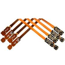
How do you ensure quality in rigid flex board production?
After the board layout is completed, it is sent to a component supplier for assembly. Traditionally, the assembling of components was done manually with a pair of tweezers. However, automated pick-and-place machines are now used to reduce the time and error of this step. The next step is the lamination process. Typically, the flex and rigid sections are glued together with hot melt adhesives, such as urethane or epoxy. This is followed by a curing cycle, which is usually around 30 minutes.
During the lamination process, it is important to maintain consistent tension between the flex and rigid sections of the board. Failure to do so can result in a lack of stability when flexing the PCB. Moreover, it can cause the flexible section to crack and break.
To avoid this issue, it is a good idea to use PCB stiffeners on the edges of the flex section. This is especially important if your design uses plated through holes or vias. The addition of tabs and anchors to these vias also helps prevent peeling during flexing.
Additionally, it is essential to keep the flex area free of discontinuities such as holes, cut-outs, and slits. These can create stress and cracks in the flex section during bending, which can lead to intermittent responses and other issues after the product is soldered on.
Expanding on the topic, rigid-flex boards represent an important advancement in printed circuit board technology, addressing limitations posed by traditional rigid or flexible PCBs used individually. As electronic devices continue to evolve with higher levels of integration and functionality, rigid-flex PCBs have become indispensable for applications demanding compact designs, reliability, and enhanced performance.
Finally, it is important to keep the thickness of the flex section consistent with that of the rigid portion. This will help avoid the flex section from becoming too thin and susceptible to thermal expansion and contraction.