
Electrical Testing Procedures for Flex Circuits
Electrical testing is an indispensable tool for ensuring the safety, efficiency, and compliance of many engineering projects. From routine diagnostics to advanced maintenance techniques, the rigor of these tests plays an important role in preventing costly and hazardous system failures. The latest advancements in technology are transforming the industry, enabling more accurate and comprehensive testing with greater speed and user-friendly interfaces. Nevertheless, despite the countless benefits of these advances, it is still critical for engineers to understand the core concepts and procedures that underlie advanced electrical testing.
Flex circuits are essential components in modern electronic devices. They provide the flexibility required for compact, lightweight designs, as well as the reliability needed to meet demanding performance criteria. For example, the flex ribbon cables in inkjet printers must be designed to withstand repeated bending and unbending cycles without suffering damage or loss of functionality. To achieve this goal, static bend-to-fit applications require a specialized approach to materials and layer constructions.
In contrast, dynamic flex circuits must be able to adapt to changes in physical structure, as well as to the environmental conditions they will encounter in use. Consequently, they require special test and measurement tools to assess their ability to withstand mechanical stress. Using automated test equipment, engineers can evaluate the stability of a flexible circuit by measuring parameters like resistance, capacitance, and impedance. They can also test for defects like open and short circuits.
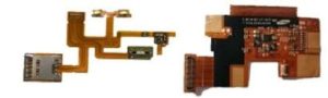
What Are the Electrical Testing Procedures for Flex Circuits?
A comprehensive flex circuit evaluation must include a number of other tests, including reliability testing and environmental testing. These tests simulate the aging of a flexible circuit, and allow manufacturers to identify potential weak points in their design or manufacturing processes. They can also be used to predict how long a circuit will retain its functionality and integrity.
Moreover, electrical testing can help improve energy efficiency in systems by pinpointing areas of waste and inefficiency. This allows engineers to reduce the energy consumption of a system, while maintaining operational functionality. Routine and thorough testing can also prevent issues like corrosion and oxidation, which can impact the performance of electrical components and cables.
Another important function of electrical testing is to check the integrity of solder connections. This can be accomplished through a variety of methods, including flying probe testing and in-circuit test (ICT). Flying probe tests use fixed probes laid out to match the PCB design and check the consistency of each solder connection. ICT uses a bed of probes to push down on the board, checking for consistent pressure that will hold solder connections in place. Both of these test methods have their pros and cons, and the best choice depends on the specific needs of the project at hand.
Other key tests for flex circuits include insulation resistance testing, which can detect breaks in the dielectric strength of cables and components, and earth testing, which checks the effectiveness of an earth electrode system to divert fault currents to ground. This test is particularly crucial for high-voltage electrical installations, and helps ensure the safety of personnel and equipment by allowing fault currents to be discharged safely.